| Disassembling a Dell Latitude CPx J650GT notebook |
|
I bought this laptop used sometime late in 2003, at which point it was about 3 years old. It worked without issue
for awhile, until the bearing in the cooling fan wore out near the end of December. Whenever it
ran, it would make a loud rattling sound, and under heavy load (I run distributed computing projects for TeAm
Anandtech on it 24/7) the CPU would get dangerously hot, as high as 60° C if /proc/acpi/thermal_zone/THM/temperature
is to be believed. A replacement was needed, so I decided to take the laptop apart piece by piece to see what sort of
fan I had to deal with. Step 1: Prepare for battle Before I could start tearing apart this beast, I first needed to clear off some space and gather my tools. The tools you will need during this adventure are:
With my workspace ready and my tools in reach, I got to work:
1. Shut down the laptop and unplug it.
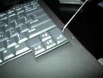
Step 2: Remove the keyboard Now we're getting serious. :)
6. Take out the screws labeled "K" on the bottom of the laptop.
9. Lay the keyboard over the left side of the laptop, upside down.
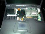
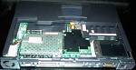
11. Put the keyboard aside. You now have most of the motherboard exposed. This should be enough for most internal maintainence, but in this case I need to go even further. Below is an annotated look at the exposed inside of the laptop. The cable labeled "X" is the display cable, and the one labeled "Y" is the palmrest cable. Keep these in mind, I will refer to them later.
Step 3: Remove the display I need to remove the motherboard, and to do that I need to remove the palmrest, and to do that I need to remove the screen.
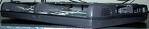
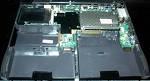
12. Unplug the display cable by pulling up on it. Now the display has been removed, and the laptop feels MUCH lighter, and also a lot more flimsy. You're looking at something like this:
Step 4: Remove the palmrest It is now time to clear the final obstacle that stands between you and the motherboard: the palmrest.
18. Unplug the palmrest cable by pulling up on it. With that gone, you now have a circuit board in a plastic tray:
Step 5: Remove the motherboard For what I have to do, this normally unneccessary step is neccessary.
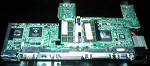
19. Loosen the screws under the PC card slot and to the right of the CPU assembly. We've seen about enough of the top of the motherboard, so here's the seldom-seen back of it:
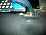
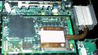
21. At this point you might want to remove the RAM, to eliminate any possibility of it being damaged. By now I had easy access to the fan, which I could see now was a 30x5mm Sunon GM0503PEB1-8. I guess maglev bearing technology isn't very good, considering the thing only lasted 3 years. To remove it, I need to remove the heatsink assembly. Step 6: Remove the CPU RF shield Not only is the heatpipe contact plate underneath the RF shield, but the shield itself blocks the heatsink screws.
22. Loosen the 3 recessed screws at the inside corners of the shield, and the 2 screws at the corners of the heatpipe contact plate. Step 7: Remove the heatsink assembly The final step of the process is to remove the heatsink assembly. In the picture below you can see the heatsink itself (1), the heatpipe contact plate (2), and the screws from hell that must be removed (3).
25. Unplug the fan cable. That's it. The laptop has been completely dismantled piece by piece. Good luck putting it back together. As a bit of an epilogue, I was unable to find a suitable replacment fan, so I bought a whole new heatsink assembly on eBay. It cost me $18, but I doubt I could find a cheaper solution. And as a bonus for reading so far, here's a "blooper reel" of everything I did wrong the first time around:
|